
In this blog post, we’ll explore how to write code that mimics physical silicon. We will create and integrate a virtual temperature sensor and expose it to the BMC’s (baseboard management controller) processor - effectively simulating the process of soldering a physical IC (integrated circuit) onto a motherboard. We will use QEMU to emulate an Aspeed AST2600 EVB board and “wire” our sensor, providing a virtual sandbox for OpenBMC, a popular Linux distro for BMCs in data center, high-performance computing systems, and telecommunication environments.
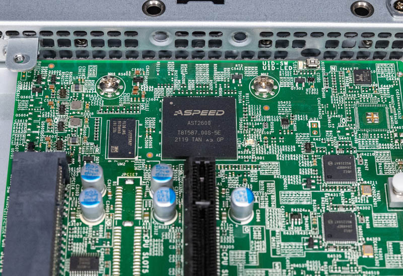 A top-down view of an AST2600 board. While the AST2600 SoC (center square chip) handles the processing, the surrounding board provides the physical interfaces we are emulating in QEMU.
Initial setup & downloads
First, we’ll clone the QEMU source code from the official repository. We also need an OpenBMC firmware image compatible with the AST2600 hardware. I’m using the ast2600-default-obmc.tar.gz release from Aspeed’s OpenBMC fork. Once unzipped, the key file is ast2600-flash.mtd - this represents the full SPI flash content that QEMU will use to boot our virtual BMC.
Creating the sensor
We’re now ready to model the sensor virtually via written code. To keep the silicon logic simple, let’s model our device after an I2C temperature sensor. I2C is a two-wire serial protocol that allows the BMC (the master) to communicate with peripheral chips (the slaves) using a shared clock (via SCL line) and data line (via SDA line). I will also briefly touch on the I2C communication protocol in later sections. Our virtual sensor will mimic a simple chip that reports the temperature when we probe it with i2cget from the BMC. To make it testable, we’ll allow the sensor to be writable via i2cset as well.
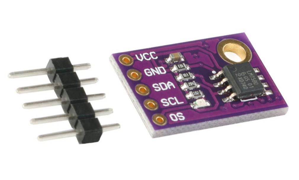 LM75, a widely popular I2C temperature sensor (foreshadow alert)
In QEMU’s codebase, navigate to hw/i2c and create a my_sensor.c file. In this file, we’ll write C code to emulate the sensor’s silicon logic, specifically focusing on the realize(), recv(), and send() functions. The realize() handler acts as the constructor and is called during device initialization. The recv() and send() are the data flow triggered when we later execute i2cget and i2cset from the OpenBMC shell.
Setting up boilerplate code
Start by define our sensor device’s identity and its internal state:
1
2
3
4
5
6
7
#define TYPE_MY_SENSOR "my_sensor"
OBJECT_DECLARE_SIMPLE_TYPE(MySensorState, MY_SENSOR)

struct MySensorState {
    I2CSlave parent_obj;
    uint8_t temperature;
};
OBJECT_DECLARE_SIMPLE_TYPE is a macro that generates other helpful macros, such as MY_SENSOR(), which we’ll use very soon below. MY_SENSOR() allows us to convert a generic DeviceState* pointer to our specific MySensorState.
In QEMU, every device is an object. Our sensor additionally inherits from the I2C slave class, allowing itself to live on an I2C bus.
The realize function
This handler is the equivalent of “hardware power-on” before the simulation starts. We’ll give our sensor a default room temperature of 26°C.
1
2
3
4
5
static void my_sensor_realize(DeviceState *dev, Error **errp) {
    MySensorState *ms = MY_SENSOR(dev);

    ms->temperature = 26;
}
The recv function
The recv handler is triggered when the I2C master (the BMC) performs a read operation. When users call i2cget targeting our sensor’s bus and address, we want to return the temperature stored in the sensor’s state.
1
2
3
4
5
static uint8_t my_sensor_recv(I2CSlave *s) {
    MySensorState *ms = MY_SENSOR(s);

    return ms->temperature;
}
In the real world, the BMC (I2C master controller) would physically toggle the SCL (clock) line upon the i2cget command. The sensor chip detects these pulses and begins flipping the voltage on the SDA (data) line to transmit bits. In our virtual version, we skip the physics - QEMU simply calls this C function and passes the return value back to the emulated BMC processor as if it had just traveled across a soldered line.
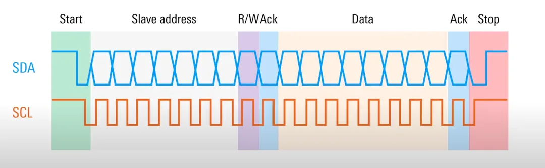 I2C protocol diagram, showing SCL and SDA. In our example, the BMC is the I2C master and the sensor is the I2C slave.
The send function
Similarly, the send handler is triggered when the I2C master performs a write operation. When users call i2cset to set the data at our sensor’s bus and address, we want to update the temperature stored in the sensor’s state and return 0 as success.
1
2
3
4
5
6
static int my_sensor_send(I2CSlave *s, uint8_t data) {
    MySensorState *ms = MY_SENSOR(s);

    ms->temperature = data;
    return 0;
}
During an i2cset command in the real world, the BMC controller physically drives the data line, “pushing” bits towards the sensor. The sensor chip would receive these bits into a shift register and then latch them into internal memory.
Connecting the dots: class_init
Now that we’re done with the silicon logic, we need to bridge the implementation and the generic I2CSlave and Device classes. This is done via class_init, in which we bind our handlers to the function pointers of said classes.
Our sensor is both a “Device” and an “I2C Slave” in the context of QEMU Object Model (QOM). “Device” is its base identity and the realize function is declared here as every device needs to be “realized”. The recv and send handlers are specific to the I2C protocol, and therefore we bind our custom implementation to our sensor’s I2CSlaveClass identity. We utilize macros such as DEVICE_CLASS() and I2C_SLAVE_CLASS() to obtain the different identities of the same my_sensor instance. Each sensor type (model) we define will have its own Device instance, and if it’s an I2C sensor, its own I2CSlaveClass instance. This allows different sensor models to have different handler implementations, while multiple instances of the same sensor model to share the same handler implementation without duplicating function pointers and wasting memory.
1
2
3
4
5
6
7
8
static void my_sensor_class_init(ObjectClass *klass, const void *data) {
    DeviceClass *dc = DEVICE_CLASS(klass);
    I2CSlaveClass *sc = I2C_SLAVE_CLASS(klass);

    dc->realize = my_sensor_realize;
    sc->recv = my_sensor_recv;
    sc->send = my_sensor_send;
}
Wrapping up my_sensor.c
As the final step of modeling our custom sensor, we’ll register this new class with QEMU’s central object system at the bottom. Here is the full code of my_sensor.c:
1
2
3
4
5
6
7
8
9
10
11
12
13
14
15
16
17
18
19
20
21
22
23
24
25
26
27
28
29
30
31
32
33
34
35
36
37
38
39
40
41
42
43
44
45
46
47
48
49
50
51
52
53
54
55
#include "qemu/osdep.h"
#include "hw/i2c/i2c.h"
#include "qom/object.h"

// 1. Define the boilerplate
#define TYPE_MY_SENSOR "my_sensor"
OBJECT_DECLARE_SIMPLE_TYPE(MySensorState, MY_SENSOR)

struct MySensorState {
    I2CSlave parent_obj;
    uint8_t temperature;
};

// 2. Define the realize, read (i2cget), and write (i2cset) logic
static void my_sensor_realize(DeviceState *dev, Error **errp) {
    MySensorState *ms = MY_SENSOR(dev);

    ms->temperature = 26;
}

static uint8_t my_sensor_recv(I2CSlave *s) {
    MySensorState *ms = MY_SENSOR(s);

    return ms->temperature;
}

static int my_sensor_send(I2CSlave *s, uint8_t data) {
    MySensorState *ms = MY_SENSOR(s);

    ms->temperature = data;
    return 0;
}

// 3. Setup the class
static void my_sensor_class_init(ObjectClass *klass, const void *data) {
    DeviceClass *dc = DEVICE_CLASS(klass);
    I2CSlaveClass *sc = I2C_SLAVE_CLASS(klass);

    dc->realize = my_sensor_realize;
    sc->recv = my_sensor_recv;
    sc->send = my_sensor_send;
}

static const TypeInfo my_sensor_info = {
  .name = TYPE_MY_SENSOR,
  .parent = TYPE_I2C_SLAVE,
  .instance_size = sizeof(MySensorState),
  .class_init = my_sensor_class_init,
};

static void my_sensor_register_types(void) {
    type_register_static(&my_sensor_info);
}

type_init(my_sensor_register_types)
“Soldering” the sensor
We’re ready to mount our sensor to the motherboard! In QEMU, this happens during the machine (in our case, the Aspeed AST2600 EVB) initialization code. Navigate to hw/arm/aspeed_ast2600_evb.c and add the following one-liner to the bottom of ast2600_evb_i2c_init function:
1
2
3
4
5
6
7
8
9
static void ast2600_evb_i2c_init(AspeedMachineState *bmc)
{
    AspeedSoCState *soc = bmc->soc;
    uint8_t *eeprom_buf = g_malloc0(8 * 1024);

    ...

+   i2c_slave_create_simple(aspeed_i2c_get_bus(&soc->i2c, 8), "my_sensor", 0x48);
}
This instruction tells QEMU to instantiate our custom silicon and attach it to bus 8 of the AST2600 board at address 0x48. From the perspective of the BMC’s Linux kernel, this is indistinguishable from a physical sensor IC being wired to the I2C topology. When we eventually boot the system, the kernel’s I2C driver will probe this bus, and our emulated logic will be there to respond.
Hardware Note: QEMU assumes an ideal I2C bus with perfect signal integrity and infinite pull-up strength. In the real world when soldering such hardware, we’d be reaching for a pair of pull-up resistors to maintain a “logic HIGH” (typically 3.3V) when idle for the SDA and SCL lines. In QEMU, there is no need to worry about bus capacitance and voltage levels.
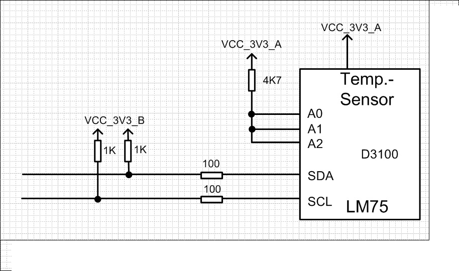 I2C temperature sensor diagram, notice the pull-up resistors connected to SDA and SCL
Compiling and running QEMU
Modifying the build script
Before we can compile, we need to let QEMU’s build system know that our new C file exists. QEMU uses Meson and Ninja for its build process. Navigate to hw/i2c/meson.build and add my_sensor.c to the i2c_ss source set. (See more about Meson + Ninja in a later section.)
We’ll add our file to the statement gated by CONFIG_ASPEED_SOC, so that whenever Aspeed support is enabled, our file is included properly.
1
2
3
4
5
6
- i2c_ss.add(when: 'CONFIG_ASPEED_SOC', if_true: files('aspeed_i2c.c'))

+ i2c_ss.add(when: 'CONFIG_ASPEED_SOC', if_true: files(
+   'aspeed_i2c.c',
+   'my_sensor.c'
+ ))
Configure the build
From the root of our QEMU codebase, create a build folder and configure it. Since we are targeting the AST2600 (which is an ARM-based SoC), we need the arm-softmmu target.
1
2
% mkdir build && cd build
% ../configure --target-list=arm-softmmu
Compile with Ninja
Use the following command to compile the QEMU source code with ninja. Ninja automatically leverages multiple CPU cores to compile in parallel.
1
% ninja -C build
Quick side-note on Meson and Ninja
Meson and Ninja are two popular build tools that are often used together. Typically in a modern build system, we have two phases:
- Phase 1 Configure - figure out what needs to be compiled and lay out a build plan.
- Phase 2 Build - execute the build plan.
In the case of Meson + Ninja, Meson handles Phase 1 while Ninja handles Phase 2.
Previously when we added our sensor source file, we also modified a meson.build file - meson.build is the human-facing layer that lets developer describe the project including sources, targets, and build options. From this file, Meson generates a build plan for Ninja to execute. Ninja is “intentionally dumb but fast” - it does not have fancy scripting or macro features like traditional Make does, but it also allows Ninja to be more efficient than Make. Ninja reads its Ninja input files (.ninja etc), which are meant to be machine-generated by tools capable of handling Phase 1, such as Meson or CMake. Ninja files are not meant to be edited by hand.
Launching the emulation
We’re finally ready to launch the AST2600 EVB with our OpenBMC image! From the build/ directory, run the following command:
1
2
3
4
% ./qemu-system-arm -m 1G \
    -M ast2600-evb \
    -drive file=path/to/ast2600-flash.mtd,format=raw,if=mtd \
    -nographic
When prompted, the default username is root and the password is 0penBmc (note the 0 (zero) instead of O).
P.s. The flag -m sets the startup RAM size to 1G. -M specifies the machine (in our case, Aspeed AST2600 EVB). -drive ..... if=mtd loads the OpenBMC image into virtual flash memory. Lastly, -nographic disables graphical output and diverts the BMC’s serial console directly to your terminal.
Final verification
Wait for the kernel to finish booting and we should arrive at the BMC prompt.
Detecting the sensor
At the BMC prompt, we can scan bus 8 to verify our “soldering” job:
1
2
3
4
5
6
7
8
9
10
11
# i2cdetect -y 8

     0  1  2  3  4  5  6  7  8  9  a  b  c  d  e  f
00:                         -- -- -- -- -- -- -- --
10: -- -- -- -- -- -- -- -- -- -- -- -- -- -- -- --
20: -- -- -- -- -- -- -- -- -- -- -- -- -- -- -- --
30: -- -- -- -- -- -- -- -- -- -- -- -- -- -- -- --
40: -- -- -- -- -- -- -- -- 48 -- -- -- -- UU -- --
50: -- -- -- -- -- -- -- -- -- -- -- -- -- -- -- --
60: -- -- -- -- -- -- -- -- -- -- -- -- -- -- -- --
70: -- -- -- -- -- -- -- --
Seeing 48 at address 0x48 (determined by row and column) is a major win - it means QEMU has successfully wired our C logic to the virtual I2C bus.
We also notice there are two different types of responses for active devices, numerical (48 in our case) and UU.
A raw numerical response like 48 indicates that a device responded at the address 0x48, but no kernel driver is currently managing it. The bus is signaling that “something is here physically”, but the OS hasn’t claimed it yet. Tying the sensor to a driver in the BMC kernel’s device tree (DTS) or even developing a custom driver for the sensor would be a natural follow-up exercise and a great topic for a future blog post.
On the other hand, UU stands for “Unit Busy.” It means a device is present (at 0x4d in our example, as determined by row and column), and a kernel driver has successfully probed and “claimed” it. The kernel has locked this address to prevent userspace tools from accidentally interfering with the driver’s communication. If you dive into the DTS source code of our OpenBMC image we should see 0x4d on bus 8 being explicitly matched to a kernel driver. In fact, since 8-0x4d is a properly-managed device, we can probe it to check its name:
1
2
# cat /sys/bus/i2c/devices/8-004d/name
lm75
It turns out it’s an actual LM75 temperature sensor instance that QEMU and OpenBMC have defined together.
Reading the temperature from our sensor
Use i2cget to trigger our recv function of our sensor at bus 8 address 0x48. In actual silicon, the sensor chip would toggle I2C’s SDA line to send the bits of temperature data to the BMC.
1
2
# i2cget -y 8 0x48
0x1a
0x1a is the hexadecimal value of 26, which is the correct default room temperature we set upon device init.
Overriding the temperature of our sensor
Use i2cset to trigger our send logic and set 32 degrees (0x20 in hex). The physical equivalent would be the BMC driving the voltage transitions of the SDA line to shift data over to the sensor chip, who takes the bits and stores them in an internal register.
1
i2cset -y 8 0x48 0x20
A subsequent i2cget read should output 0x20 back to us. Note that we are allowed to inject the temperature only because we implemented the send logic in QEMU. With a real-world temperature sensor, its temperature register is typically read-only, as its value is determined by physical temperature. A i2cset call would likely result in a write failure.
Conclusion
If you’ve always wanted to dive into the low-level embedded world but felt gated by the availability of physical hardware, QEMU can be a perfect tool to help move the process entirely into the software domain.
For BMC software engineers, QEMU decouples software/firmware from the silicon. It allows us to develop kernel device drivers and orchestration logic months before a new generation of motherboard is even manufactured. Furthermore, we get to stress-test scenarios that are physically dangerous or difficult to reproduce - e.g. extreme thermal events or specific power sequencing failures - all within a safe, cost-free, and repeatable environment.
On the other hand, for non-embedded software engineers who find hardware a bit of a “black box,” digging into the QEMU source code is a great way to inspect hardware orchestration through the lens of programming - a “language” we already understand intuitively.
Whichever category you fall into, I hope you enjoyed this blog post and even learned a thing or two. That’s all for today, until next time and happy hacking!